Method

Scene Motion Decomposition for Learnable Visual Odometry [SMD-LVO]
https://github.com/saic-vul/odometry

Submitted on 12 Dec. 2019 15:48 by
Anna Vorontsova (Samsung AI Center Russia)

Running time:0.03 s
Environment:GPU @ 2.5 Ghz (Python)

Method Description:
Optical Flow (OF) and depth are commonly used for
visual odometry since they provide sufficient
information about camera ego-motion in a rigid
scene. We reformulate the problem of ego-motion
estimation as a problem of motion estimation of a
3D-scene with respect to a static camera. The
entire scene motion can be represented as a
combination of motions of its visible points.
Using OF and depth we estimate a motion of each
point in terms of 6DoF and represent results in
the form of motion maps, each one addressing
single degree of freedom. In this work we provide
motion maps as inputs to a deep neural network
that predicts 6DoF of scene motion. Through our
evaluation on outdoor and indoor datasets we show
that utilizing motion maps leads to accuracy
improvement in comparison with naive stacking of
depth and OF. Another contribution of our work is
a novel network architecture that efficiently
exploits motion maps and outperforms learnable
RGB/RGB-D baselines.
Parameters:
supervised=True
Latex Bibtex:
@misc{slinko2019scene,
title={Scene Motion Decomposition for
Learnable Visual Odometry},
author={Igor Slinko and Anna Vorontsova and
Filipp Konokhov and Olga Barinova and Anton
Konushin},
year={2019},
eprint={1907.07227},
archivePrefix={arXiv},
primaryClass={cs.CV}
}

Detailed Results

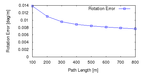
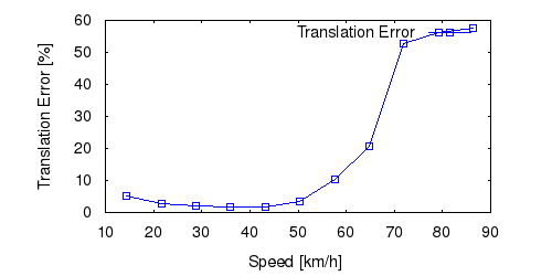
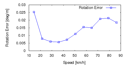
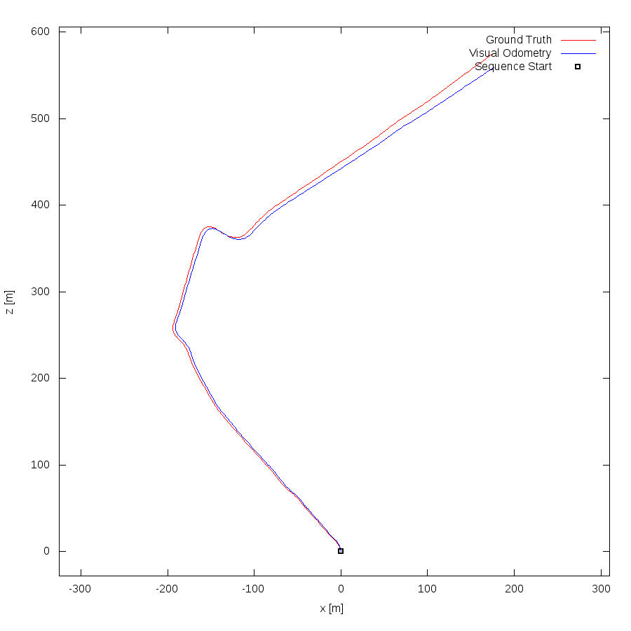
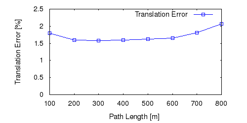
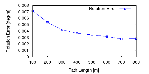
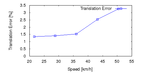
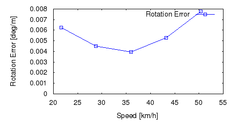
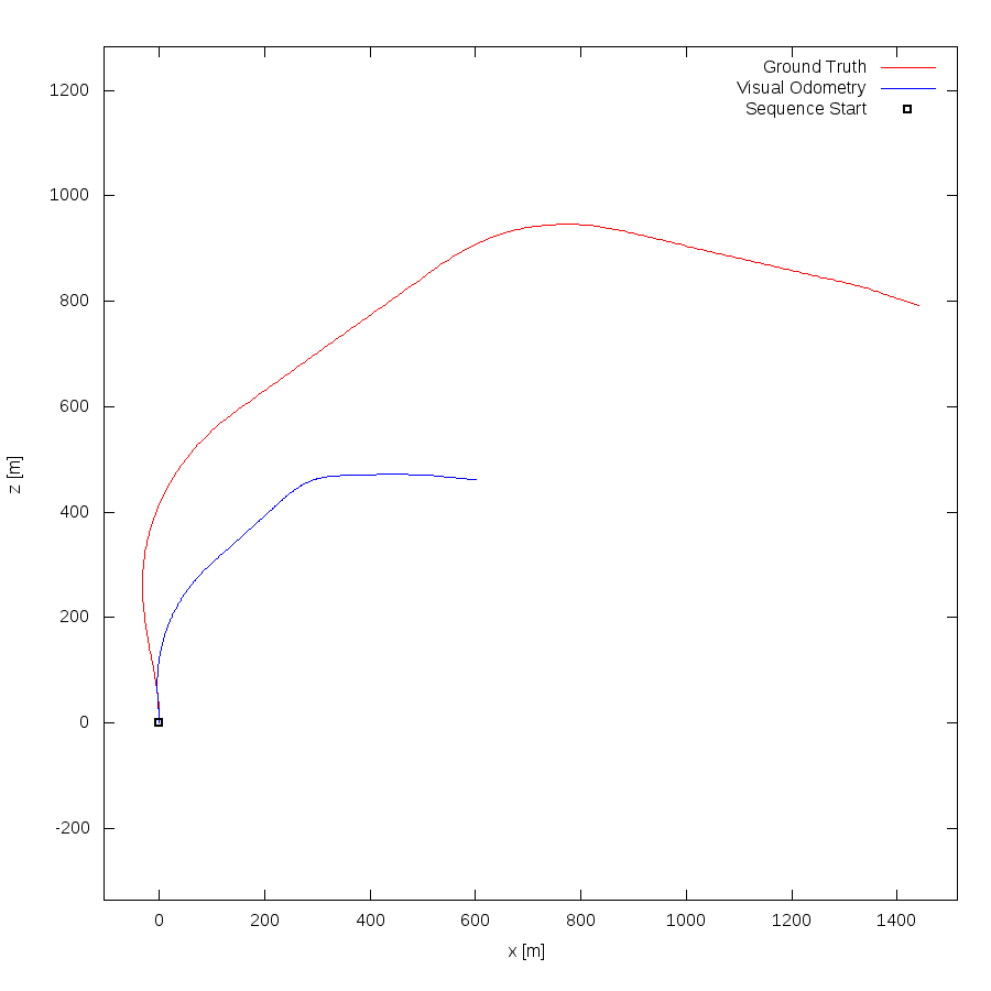
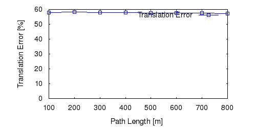
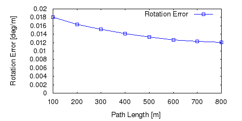
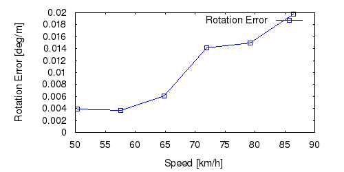
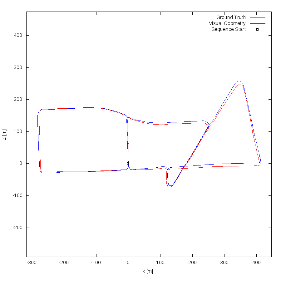
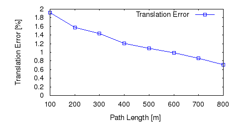
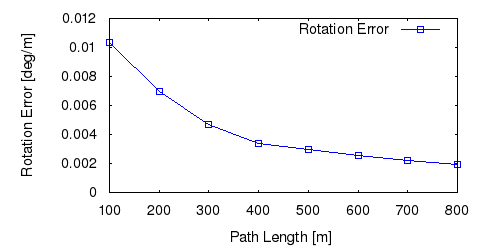
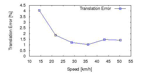
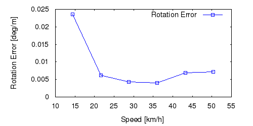
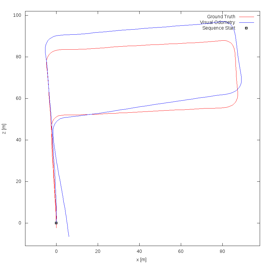
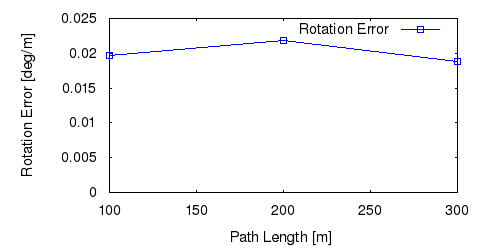
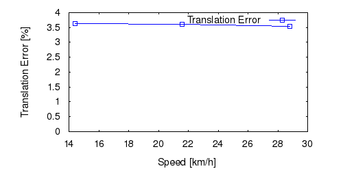
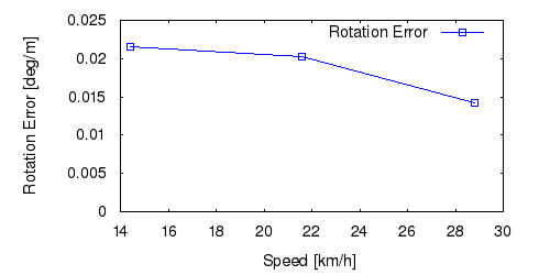
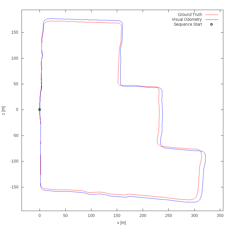
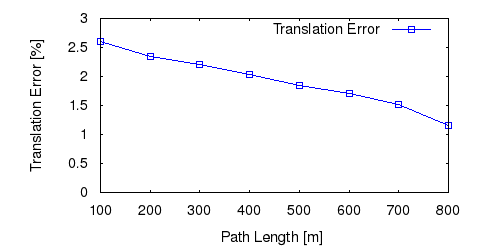
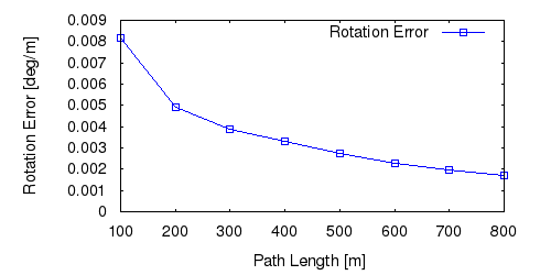
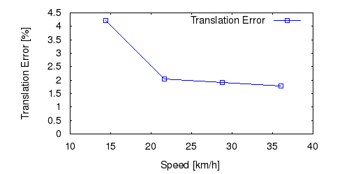
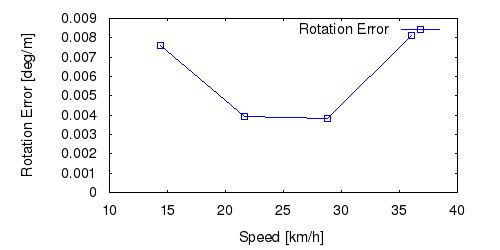
From all test sequences (sequences 11-21), our benchmark computes translational and rotational errors for all possible subsequences of length (5,10,50,100,150,...,400) meters. Our evaluation ranks methods according to the average of those values, where errors are measured in percent (for translation) and in degrees per meter (for rotation). Details for different trajectory lengths and driving speeds can be found in the plots underneath. Furthermore, the first 5 test trajectories and error plots are shown below.

Test Set Average


This figure as: png eps pdf txt gnuplot


This figure as: png eps pdf txt gnuplot


This figure as: png eps pdf txt gnuplot


This figure as: png eps pdf txt gnuplot


Sequence 11


This figure as: png eps pdf txt gnuplot


This figure as: png eps pdf txt gnuplot


This figure as: png eps pdf txt gnuplot


This figure as: png eps pdf txt gnuplot


This figure as: png eps pdf txt gnuplot


Sequence 12


This figure as: png eps pdf txt gnuplot


This figure as: png eps pdf txt gnuplot


This figure as: png eps pdf txt gnuplot


This figure as: png eps pdf txt gnuplot


This figure as: png eps pdf txt gnuplot


Sequence 13


This figure as: png eps pdf txt gnuplot


This figure as: png eps pdf txt gnuplot


This figure as: png eps pdf txt gnuplot


This figure as: png eps pdf txt gnuplot


This figure as: png eps pdf txt gnuplot


Sequence 14


This figure as: png eps pdf txt gnuplot


This figure as: png eps pdf txt gnuplot


This figure as: png eps pdf txt gnuplot


This figure as: png eps pdf txt gnuplot


This figure as: png eps pdf txt gnuplot


Sequence 15


This figure as: png eps pdf txt gnuplot


This figure as: png eps pdf txt gnuplot


This figure as: png eps pdf txt gnuplot


This figure as: png eps pdf txt gnuplot


This figure as: png eps pdf txt gnuplot


eXTReMe Tracker