
Folder Structure
{seq:0>4} denotes the sequence ID using 4 digits and {frame:0>10} denotes the frame ID using 10 digits.
  KITTI-360/
  |-- calibration/
  │   |-- calib_cam_to_pose.txt
  │   |-- calib_cam_to_velo.txt
  │   |-- calib_sick_to_velo.txt
  |   |-- perspective.txt
  │   |-- image_02.yaml
  │   `-- image_03.yaml
  |-- data_2d_raw/
  |   `-- 2013_05_28_drive_{seq:0>4}_sync/
  |       |-- image_{00|01}/
  |       |   |-- data_rect/
  |       |   |   `-- {frame:0>10}.png
  |       |   |-- data_rgb/
  |       |   |   `-- {frame:0>10}.png
  |       |   `-- timestamps.txt
  |       `-- image_{02|03}/
  |           |-- data_rgb/
  |           |   `-- {frame:0>10}.png
  |           `-- timestamps.txt
  |-- data_2d_semantics/
  │   |-- train
  |   |   |-- 2013_05_28_drive_train_frames.txt
  |   |   |-- 2013_05_28_drive_val_frames.txt
  |   |   `-- 2013_05_28_drive_{seq:0>4}_sync/
  |   |      |-- image_{00|01}/
  |   |      |    |-- semantic/
  |   |      |    |   `-- {frame:0>10}.png
  |   |      |    |-- semantic_rgb/
  |   |      |    |   `-- {frame:0>10}.png
  |   |      |    |-- instance/
  |   |      |    |   `-- {frame:0>10}.png
  |   |      |    `-- confidence/
  |   |      |        `-- {frame:0>10}.png
  |   |      `--  instanceDict.json
  |   ...
  |-- data_3d_raw/
  |   `-- 2013_05_28_drive_{seq:0>4}_sync/
  |       |-- velodyne_points/
  |       |   |-- data/
  |       |   |   `-- {frame:0>10}.bin
  |       |   `-- timestamps.txt
  |       `-- sick_points/
  |           |-- data/
  |           |   `-- {frame:0>10}.bin
  |           `-- timestamps.txt
  |-- data_3d_semantics/
  │   |-- train
  |   |   |-- 2013_05_28_drive_train.txt
  |   |   |-- 2013_05_28_drive_val.txt
  |   |   `-- 2013_05_28_drive_{seq:0>4}_sync/
  |   |      |-- static/
  |   |      |    `-- {start_frame:0>10}_{end_frame:0>10}.ply
  |   |      `-- dynamic/
  |   |           `-- {start_frame:0>10}_{end_frame:0>10}.ply
  │   `-- test
  |       `-- 2013_05_28_drive_{seq:0>4}_sync/
  |          `-- static/
  |               `-- {start_frame:0>10}_{end_frame:0>10}.ply
  |-- data_3d_bboxes/
  |   |-- train
  |   |   `-- 2013_05_28_drive_{seq:0>4}_sync.xml
  |   `-- train_full
  |       `-- 2013_05_28_drive_{seq:0>4}_sync.xml
  `-- data_poses/
      `-- 2013_05_28_drive_{seq:0>4}_sync/
          |-- poses.txt
          |-- cam0_to_world.txt
          `-- oxts/
              |-- data/
              |   `-- {frame:0>10}.txt
              |-- dataformat.txt
              `-- timestamps.txt
Development Toolkit
2D Data Format
-
data_2d_raw/2013_05_28_drive_{seq:0>4}_sync/image_{00|01}/data_rect/{frame:0>10}.png:
Rectified stereo pairs in 8-bit PNG format. Our 2D semantic & instance labels are provided for these rectified images. -
data_2d_raw/2013_05_28_drive_{seq:0>4}_sync/image_{00|01}/data_rgb/{frame:0>10}.png:
Raw, unrectified stereo pairs in 8-bit PNG format. -
data_2d_raw/2013_05_28_drive_{seq:0>4}_sync/image_{00|01}/timestamps.txt:
Timestiamps of perspective images, each line contains the timestamp of one image. -
data_2d_raw/2013_05_28_drive_{seq:0>4}_sync/image_{02|03}}/data_rgb/{frame:0>10}.png:
Fisheye images in 8-bit PNG format. -
data_2d_raw/2013_05_28_drive_{seq:0>4}_sync/image_{02|03}/timestamps.txt:
Timestiamps of fisheye images, each line contains the timestamp of one image.
-
data_2d_semantics/train/2013_05_28_drive_{seq:0>4}_sync/image_{00|01}/semantic/{frame:0>10}.png:
Semantic label in single-channel 8-bit PNG format. Each pixel value denotes the correspondingsemanticID. -
data_2d_semantics/train/2013_05_28_drive_{seq:0>4}_sync/image_{00|01}/semantic_rgb/{frame:0>10}.png:
Semantic RGB image in 3-channel 8-bit PNG format. Each pixel value denotes the color-coded semantic label. -
data_2d_semantics/train/2013_05_28_drive_{seq:0>4}_sync/image_{00|01}/instance/{frame:0>10}.png:
Instance label in single-channel 16-bit PNG format. Each pixel value denotes the correspondinginstanceID. Here,instanceID = semanticID*1000 + classInstanceIDwithclassInstanceIDdenoting the instance ID within one class andclassInstanceID = 0for classes without instance label. Note thatinstanceIDis unique across the full sequence, for example, a building appearing in different frames has the sameinstanceIDin all these frames. -
data_2d_semantics/train/2013_05_28_drive_{seq:0>4}_sync/image_{00|01}/confidence/{frame:0>10}.png:
Confidence map in single-channel 16-bit PNG format. Each pixel value corresponds to a confidence score ranging from 0 to 65535. Lower values suggest lower confidence.
3D Data Format
-
data_3d_raw/2013_05_28_drive_{seq:0>4}_sync/velodyne_points/data/{frame:0>10}.bin:
Velodyne scans in BINARY format, defined in the Velodyne coordinates. -
data_3d_raw/2013_05_28_drive_{seq:0>4}_sync/velodyne_points/timestamps.txt:
Timestiamps of Velodyne scans, each line contains the timestamp of one scan. -
data_3d_raw/2013_05_28_drive_{seq:0>4}_sync/sick_points/data/{frame:0>10}.bin:
SICK scans in BINARY format, defined in the SICK coordinates. Note that the SICK laser scanner has a higher FPS, thus the frame indices of SICK scans do not align with those of images nor Velodyne scans. -
data_3d_raw/2013_05_28_drive_{seq:0>4}_sync/sick_points/timestamps.txt:
Timestamps of SICK scans, each line contains the timestamp of one scan.
start_frame and the end_frame (both in 10 digits):
-
data_3d_semantics/train/2013_05_28_drive_{seq:0>4}_sync/static/{start_frame:0>10}_{end_frame:0>10}.ply:
Accumulated static point clouds in PLY format for training. The PLY file contains only vertices. Each vertex of the PLY contains the following information:x y z red green blue semanticID instanceID isVisible confidence. Here,x y z(32-bit float) is the location of a 3D point in the world coordinate system,red green blue(8-bit uchar) is the color of a 3D point obtained by projecting it to adjacent 2D images,semanticId instanceID(32-bit int) describes the label of a 3D point. The binary variableisVisible(8-bit uchar) is 0 when a 3D point is not visible in any of the perspective images, and 1 otherwise. For these occluded points we keep a 3D point only if it is uniquely labeled by a 3D bounding box and assign the label according to the annotation. Unlabeled or ambiguously labeled occluded points are ignored. The last valueconfidence(32-bit float) indicates the confidence of the semantic label of a 3D point. If a 3D point is not visible in any of the frames but is uniquely labeled by a single class, we assign this unique label to the 3D point and a confidence value of 1.0. -
data_3d_semantics/train/2013_05_28_drive_{seq:0>4}_sync/dynamic/{start_frame:0>10}_{end_frame:0>10}.ply:
Accumulated dynamic point clouds in PLY format. The PLY file contains only vertices. Each vertex has an additionaltimestamp(32-bit int) value compared to the static points:x y z red green blue semantic instance isVisible timestamp. -
data_3d_semantics/test/2013_05_28_drive_{seq:0>4}_sync/static/{start_frame:0>10}_{end_frame:0>10}.ply:
Fused static point clouds in PLY format for testing. The test point clouds share the same format as the training point clouds except that labels are omitted:x y z red green blue isVisible.
-
data_3d_semantics/train/2013_05_28_drive_{seq:0>4}_sync.xml:
3D annotations of objects containing instance labels. Each elementobject{d}denotes a bounding box having consistentsemanticIdandinstanceIdwith the 2D labels. Theverticesandfacesmatrices form the mesh of the bounding box in a local coordinate. Thetransformmatrix transforms this mesh to the world coordinate. Thetimestampdenotes the frame ID for dynamic objects and is -1 for static object. -
data_3d_semantics/train_full/2013_05_28_drive_{seq:0>4}_sync.xml:
Complete 3D annotations including ground objects. Each elementobject{d}denotes a bounding primitive. Theverticesandfacesmatrices form the mesh of the bounding box in the local coordinate system of the object. Thetransformmatrix transforms this mesh to the world coordinate. Thetimestampdenotes the frame ID for dynamic objects and is -1 for static object.
Calibrations
-
calibration/calib_cam_to_pose.txt:
Each line contains a 3x4 matrix denoting the transformation from camera coordinates to GPS/IMU coordinates. There are 4 rows, including two for unrectified perspective camerasimage_00,image_01and two for fisheye camerasimage_02,image_03. -
calibration/calib_cam_to_velo.txt:
A 3x4 matrix denoting the rigid transformation from the left perspective cameraimage_00coordinates to Velodyne coordinates. -
calibration/calib_sick_to_velo.txt:
A 3x4 matrix denoting the rigid transformation from SICK laser scanner coordinates to Velodyne coordinates. -
calibration/perspective.txt:
Intrinsics of the perspective cameras. The lines starting withP_rect_00andP_rect_01provide 3x4 perspective intrinsics of the rectified perspective cameras.R_rect_00andR_rect_01correspond to 3x3 rectification matrices. -
calibration/image_{02|03}.yaml:
Intrinsics of the fisheye cameras.
Poses
-
data_poses/2013_05_28_drive_{seq:0>4}_sync/poses.txt:
Each line has 13 numbers, the first number is an integer denoting the frame index. The rest is a 3x4 matrix denoting the rigid body transform from GPU/IMU coordinates to a world coordinate system. The origin of this world coordinate system is the same for all sequences, chosen as the center of the sequences. Note that the frame indices may not be continuous, as this list only provides pose at a given frame if the moving distance between this frame and the last valid frame is larger than a threshold. This means some frames collected at a very low moving speed are neglected. -
data_poses/2013_05_28_drive_{seq:0>4}_sync/cam0_to_world.txt:
Each line has 17 numbers, the first number is an integer denoting the frame index. The rest is a 4x4 matrix denoting the rigid body transform from the rectified perspective camera coordinates to the world coordinate system. -
data_poses/2013_05_28_drive_{seq:0>4}_sync/oxts/data/{frame:0>10}.txt:
Raw OXTS measurements, including altitude, global orientation, velocities, accelerations, angular rates, accuracies and satellite information. -
data_poses/2013_05_28_drive_{seq:0>4}_sync/oxts/dataformat.txt:
Detailed documentation of the raw OXTS data. -
data_poses/2013_05_28_drive_{seq:0>4}_sync/oxts/timestamps.txt:
Timestiamps of OXTS measurements, each line contains the timestamp of one measurement.
Sensor Locations
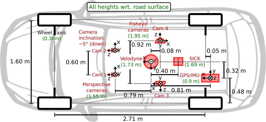
As illustrated in the figure, the coordinate systems of the sensors are defined as follows:
- Perspective cameras (
image_00,image_01): x = right, y = down, z = forward - Left fisheye camera (
image_02): x = forward, y = down, z = left - Right fisheye camera (
image_03): x = backward, y = down, z = right - Velodyne: x = forward, y = left, z = up
- GPS/IMU: x = forward, y = right, z = down
- World coordinate system: x = forward, y = left, z = up
Frequently Asked Questions
How can I project a 3D raw Velodyne scans to the image plane?
First, you need the transformation matrix from the Velodyne coordinate frame to a camera coordinate frame
Tr(velo -> cam_k). This can be obtained by subsequently applying the transformation from the Velodyne coordinate frame to the left Perspective camera Tr(velo -> cam_0) (inverting calib_cam_to_velo.txt), and the transformation from the left Perspective camera to any other camera Tr(cam_0 -> cam_k) (from calib_cam_to_pose.txt).
Next, you need to project the point in the camera coordinate frame to the corresponding image plane using the camera intrinsics. You can find our implementation of the projection for pespective cameras and fisheye cameras in our utility scrpts.
We also provide a projectVeloToImage function that implements these two steps described above and visualizes the raw Velodyne scans in the image plane.
What is the difference between poses.txt and cam0_to_world.txt?
poses.txt provides Tr(imu -> world) while cam0_to_world.txt gives Tr(cam_0 -> world). Here you can find how cam0_to_world.txt is calculated from poses.txt .